Serial Communication
In Short:
Compulsory
Part - I Basics of Serial Programming. Hardware Serial Port
- View the YouTube video for 32 minutes
- 2. Solve the assignment and go home.
Optional (Compulsory for II'nd and III'rd Year students)
Part - II Basics of Software Serial Port. Making my own Serial Transmit function.
Part - III Using the Arduino's Software Serial Library
In Detail:
Once you are done with Part-I proceed further.
Part - II Basics of Software Serial Port. Making my own Serial Transmit function.
- A hardware serial port is a communication interface that transfers information sequentially one bit at a time.
- It is used to connect devices that use serial communication, such as modems, terminals, peripherals, and computers.
- Hardware serial ports are faster than software serial ports and are used when high-speed communication is required
- They have data receive buffers
- Specifically on Arduino UNO R3 there is only one Hardware Serial Port. What if more serial ports are required?
- Using software to replicate (emulate) the functionality of Hardware serial port
- Simulate means to model, replicate, duplicate the behavior, appearance or properties of something
- Software serial ports are used when the hardware serial port is occupied by another device or when additional serial ports are required
- They are also used when the hardware serial port does not meet the requirements of the application
- A software serial port is a communication interface that allows serial communication on any digital pins (usually, non-serial port pins ie pins other than pin 0 and 1) of an Arduino board
- It is possible to have multiple software serial ports with speeds up to 115200 bps
If you connect an Oscilloscope (with appropriate configuration) to pin 13 (LED_BUILTIN),
what type of output waveform you will notice? With this code:
 // the loop function runs over and over again forever
void loop() {
  digitalWrite(LED_BUILTIN, HIGH);  // turn the LED on (HIGH is the voltage level)
  delay(100);                      // wait for a second
  digitalWrite(LED_BUILTIN, LOW);   // turn the LED off by making the voltage LOW
  delay(1000);                      // wait for a second
}
- Many companies manufactures USB to Serial converter ICs
Some examples are:
CH340 from the company WCH
CP2012 from the company Silicon Labs
FT232 from the company Fututure Technology Devices International Ltd.
Just like CH340 is a USB to Serial Converter IC, The FT232 is another IC for the same purpose made by another company.
- Download and install FT232R driver from the official web site
Another Tutorial
If you have problems with FTDI driver and want to use an older version then scroll down to bottom of this web-page.
- Connect GND pin of Arduino to the GND-pin of FT232 USB to Serial module
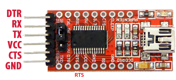
- Connect pin 13 of Arduino (acting as Tx) to the RX-pin of FT232 USB to Serial module
- Study and execute the code: soft_serial_tx_only.ino
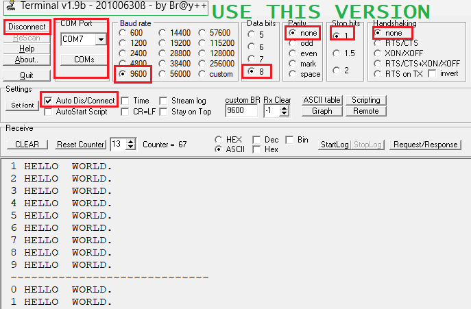
- See the output in Terminal.exe
[Use this old Terminal20100630 version only, it is stable and bug free no scrolling errors]
8N1 9600 and correct com port settings
Part - III Using the Arduino's Software Serial Library
Go to https://www.arduino.cc/reference/en/libraries/
and look for SoftwareSerial - for serial communication on any digital pins.
Click on SoftwareSerial and study the reference page.
Try Some example.
FAQ:
Q1 What is 8N1
8 data bits, No parity, 1 stop bit
Q2 What are Serial Monitor or Serial Terminal softwares other than Arduino's inbuild ?
Bray's terminal
Hyper Terminal
minicom for Linux
Q3 What are the various Escape sequences in Serial Terminal ?
Q4 What are the various Colour codes in Serial Terminal ?
Q5 What is loop back testing ?
Connect Tx to Rx
what is send is what you receive
Q6 What is NULL Modem ?
Q7 What is Hand-shaking ?
If you need an older version of the FTDI FT232 driver the click here
Please unzip (extract it before using it)