Arena

Assumptions:

Links and Joints
There are two links Link_1 and Link_2
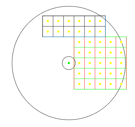
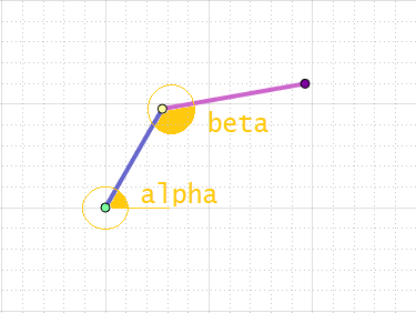
Both links are chained together.
One end of the Link_1 is pivoted to origin
The other end is jointed with Link_2
One end of Link_2, as mentioned above is pivoted to Link_1
The other end is assumed to be the tip of gripper
(on which a laser diode is mounted with focusing lens arrangement)
This mechanism will be referred as TL_RAM, as an abbreviation.

Lengths:
Length of Link_1 is 65mm
Length of Link_2 is 65mm

Arena Dimensions:
Distance between each checker is 24mm

Angle Nomenclature
Alpha: The counter-clockwise angle between the horizontal axis (X) and the Link-1 is termed as alpha (α)
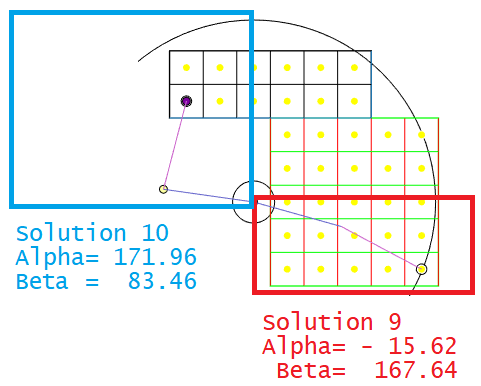
Beta: The clockwise angle between the "link-1" and link-2 is termed as beta (β)
Note: All angles are in degrees
Alpha and Beta
Deleted old defination
Home Position
Link_1 is Vertical [0, 0] to [0, L1]
Link_2 is Horizontal [0, L1] to [L2, L1]

In other words, for example:
Link_1 is Vertical [0, 0] to [0, 65]
Link_2 is Horizontal [0, 65] to [65, 65]

For some calculations, you can use this, as an initial position

[dx, dy]
dx = destination x
dy = destination y


Questions:

Programming Model: 2D-Arrays

Programming Model: 2D-Arrays
  1. Write a program to generate the following output.
    	Robot Rack: Co-ordinates for checker pick-up:
    
    	[-48.00,  96.00] [-24.00,  96.00] [  0.00,  96.00] [ 24.00,  96.00] [ 48.00,  96.00] [ 72.00,  96.00] 
    	[-48.00,  72.00] [-24.00,  72.00] [  0.00,  72.00] [ 24.00,  72.00] [ 48.00,  72.00] [ 72.00,  72.00] 
    	
  2. Write a program to generate the following output.
    	TicTacToe Game Board: Co-ordinates for checker placement:
    
    	[ 24.00,  48.00] [ 48.00,  48.00] [ 72.00,  48.00] [ 96.00,  48.00] [120.00,  48.00] 
    	[ 24.00,  24.00] [ 48.00,  24.00] [ 72.00,  24.00] [ 96.00,  24.00] [120.00,  24.00] 
    	[ 24.00,   0.00] [ 48.00,   0.00] [ 72.00,   0.00] [ 96.00,   0.00] [120.00,   0.00] 
    	[ 24.00, -24.00] [ 48.00, -24.00] [ 72.00, -24.00] [ 96.00, -24.00] [120.00, -24.00] 
    	[ 24.00, -48.00] [ 48.00, -48.00] [ 72.00, -48.00] [ 96.00, -48.00] [120.00, -48.00] 
    	
  3. Assume a line segment L1 from [0,0] to [65,0]
    If L1 is rotated counter-clockwise 30° w.r.t. origin,
    What will be the new coordinates?

  4. Assume a line segment L1 from [0,0] to [65,0]
    If L1 is rotated clockwise 30° w.r.t. origin,
    What will be the new coordinates?

  5. Assume a line segment L2 from [65,0] to [130,0]
    If L2 is rotated clockwise 30° w.r.t. [65, 0],
    What will be the new coordinates?

  6. In a TL_RAM if the arm is resting on positive horizontal axis,
    and Link_2 is rotated clockwise 30°
    What will be the new coordinates of the gripper tip?
    (consider the assumptions mentioned previously)

  7. In a TL_RAM if the arm is resting on positive horizontal axis,
    and Link_1 is rotated clockwise 45°
    What will be the new coordinates of the gripper tip?
    (consider the assumptions mentioned previously)

  8. The initial position of TL_RAM is Home Position (see assumptions)
    What will be the value of Alpha (α) and Beta (β) if [dx, dy] = [board_row_1, board_column_4] = [ 96.00, 48.00]
    HINT:
    Use basic laws of triangle
    Use elementary co-ordinate geometry
    Above all, use common sense!
    No special knowledge of Inverse Kinematics required
    Use pencil and paper, draw some sketches .....
    .. drop some perpendicular ... the usual trigonometry stuff!
    try to visualize the initial and final position of the arm .... observe the change in angles ......
    Once you solve it, do NOT share the method with other Teams
    Encourage others to find their own solution

  9. What will be the value of α and β if TL_RAM is moved to [board_row_5, board_column_5]
    Solution: [-15.62, 167.64] See figure below and verify the corctness visually


  10. What will be the value of α and β if TL_RAM is moved to [rack_row_2, rack_column_1]
    Solution: [171.96,  83.46]  See figure below and verify the corctness visually

    Solution

  11. Tabulate the values of α and β for all rack positions
    Note the minimum and maximum values of α and β
    Output format:

    Robot Rack: Co-ordinates for checker pick-up:
    [-48.00, 96.00]   [-24.00, 96.00]   [ 0.00, 96.00]   [ 24.00, 96.00]   [ 48.00, 96.00]   [ 72.00, 96.00]
    [-48.00, 72.00]   [-24.00, 72.00]   [ 0.00, 72.00]   [ 24.00, 72.00]   [ 48.00, 72.00]   [ 72.00, 72.00]

    Corresponding Rack Robot: Angles [alpha, beta] for checker pick-up:
    [ α11, β11]   [ α12, β12]   [ α13, β13]   [ α14, β14]   [ α15, β15]   [ α16, β16]
    [ α21, β21]   [ α22, β22]   [ α23, β23]   [ α24, β24]   [ α25, β25]   [ α26, β26]

    HINT:
    Alpha Beta

  12. Tabulate the values of α and β for all board positions
    Note the minimum and maximum values of α and β
    Output format: Similar to above

  13. Among all the values of α and β, rack and board combined,
    Note the minimum and maximum values of α and β

  14. Is it feasible for the Servo motors [MG996R] to move the gripper tip to [board_row_5, board_column_5] ?
    Why?

  15. If the answer to the above question is No and we still want to use the same motors,
    then what other parameters can be modified to make it feasible. What is your solution.

  16. If this constraint is introduced, what would be your solution?
    Arena grid size / pitch / center to center distance i.e., 24mm should not be changed
    Reason: assume that pine wood laser cutting for the Arena is already done

  17. If this constraint is introduced, what would be your solution?
    Arena grid size / pitch / center to center distance i.e., 24mm should not be changed
    Reason: assume that pine wood laser cutting for the Arena is already done
    and L1 should NOT be changed
    Reason: Assume that Link_1 is already 3D-printed
    What should be changed and how much ?

    HINT: One of the possible solution:
    Solution