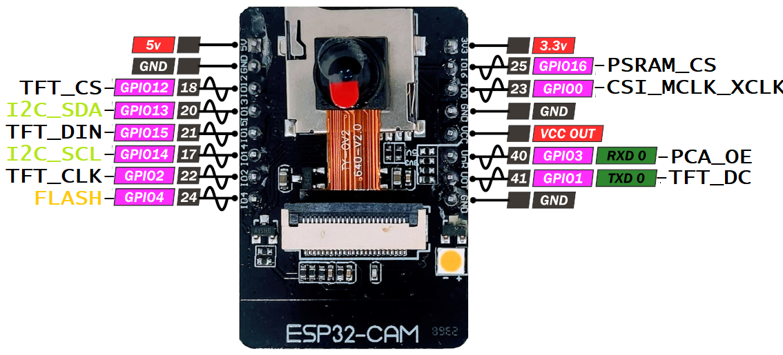
Pinout
		TFT_CS GPIO12
		TFT_DIN GPIO15
		TFT_CLK GPIO2
		TFT_DC GPIO01 TXD0
		PCA_OE GPIO03 RXD0

		FLASH   GPIO4  [Solder Pad]

		I2C_SDA GPIO13
		I2C-SCL GPIO14

		// Connect a push button to make OTA easy
		PSRAM_CS GPIO13 [Solder Pad]
		CSI_MCLK_XCLK GPIO0 [Solder Pad]

		PCA_ENABLE_PIN_NO           3  //  Fixed for TL_RAM PCB
		LED_RED_INBUILD_PIN_NO     33  //  Fixed for ESP32-CAM
		LED_FLASH_INBUILD_PIN_NO    4  //  Fixed for ESP32-CAM
To Do
- If not already done: Install (the latest version of ) ESP32 Board from Board Manager as shown in screenshot
- If not already done: Install (the latest version of ) Adafruit PWM Servo Driver library as shown in screenshot
- If not already done: Install (the latest version of ) TFT_eSPI library in Arduino IDE see screenshot
- Find the file the C:\Users\DELL\Documents\Arduino\libraries\TFT_eSPI\User_Setup.h
- Rename it to User_Setup_ORIGINAL.h
- Actually we need to replace the User_Setup.h with the modified User_Setup.h which has pin configuration according to our pin assignment decisions
- You must have the Camera Plate with ESP32-CAM and TFT display attached
- Upload the code 2023_07_14_a_Servo_Calib_Asm.zip
- Study the code carefully for Servo positions. It will be required during the robot assembly.