Sample Programs: DQCV3 |
 |
Sample Programs: DQCV3 |
 |
| SNo | Purpose | Description | Download |
|---|---|---|---|
| 1 | Serial Communication Test | Default Test Program for serial communication | Click Here |
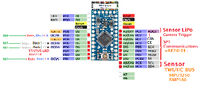
| 2 | Test Status LED of DQCV3 | Arduino ProMini: DIgital Pin 7 | Click Here |
| 3 | Test Buzzer (with Status LED) | Arduino ProMini: DIgital Pin 8 | Click Here |
| 4 | Test communication nRF24L01+ | Test 1: Simple Test:
QUADCOPTER ACTS AS RECEIVER REMOTE WORKS AS TRANSMITTER NOTE 1: Connect Serial Moniter to Quadcopter via USB NOTE 2: Connect Transmitter (Remote) with USB for power supply. Also you can use and additional Serial Moniter (Serial Terminal) Like Br@y++ |
Click Here |
| 5 | Test communication nRF24L01+ | Test 2 |
Click Here |
| 6 | I2C Scanner | Expected output:
Total devices found: 2
----------------------------------------
Scanning...
 I2C device found at address 0x68
 I2C device found at address 0x77
----------------------------------------
FYI: Typical I2C Addresses 0x0C = AK8963 (Magnetic Compass Sensor) 0x68 = MPU6050 (Gyroscope Plus Accelerometer, GY-521 board) 0x77 = BMP180 (Barometric Pressure Sensor) 0x3C = OLED 128x32 SSD1306 [011110+SA0+RW 0x3C = if SA0 is grounded ] 0x3D = OLED 128x64 SSD1306 [011110+SA0+RW 0x3D = default] |
Click Here |
| 7 | Test MPU with MultiWiiConf (GUI) |
Use Standard MultiWiicode |
|
| 8 | Test Motors 1 | Simply run motors with analogWrite | Click Here |
| 9 | Test Motors 2 | Test Motors from Remote |
No code available No code available |
| 10 | No code available | ||
| 11 | No code available | ||
| 12 | No code available | ||
| 13 | No code available |