| WR Home Topic Home | Chapter: 1 |
| <Previous | Next> |
Chapter 01
Page 8
Pin configuration simplified
Atmega328P is a very feature rich microcontroller. For the sake of developing a simple program to Blink LEDs with Atmega328P, the advanced features are not considered, just to keep it simpler.
Atmega328P Pin Configuration
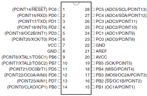 |
Detailed Pin Configuration with:
|
Atmega328P SIMPLIFIED Pin Configuration
Advanced/Secondary Pin functions omitted.
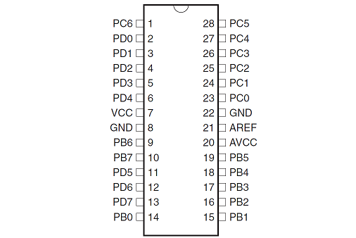
Atmega328P Pin Configuration Ports
Advanced/Secondary Pin functions omitted.
Only Port Pins and Power supply pins are considered:
PORTB has 8-pins: Pins From PB0 to PB7 8
PORTC has 7-pins: Pins From PC0 to PC6 +7
PORTD has 8-pins: Pins From PD0 to PD7 +8
TOTAL = 23 Pins
These 23 Pins can be used for Input/Output. At a particular time instant a pin can either act as an input pin OR an output pin, but not both. It can be programmatically defined that a pin will act as an input-pin OR an output-pin.
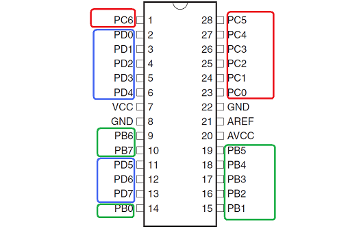
Each Port pin has a Alternate function
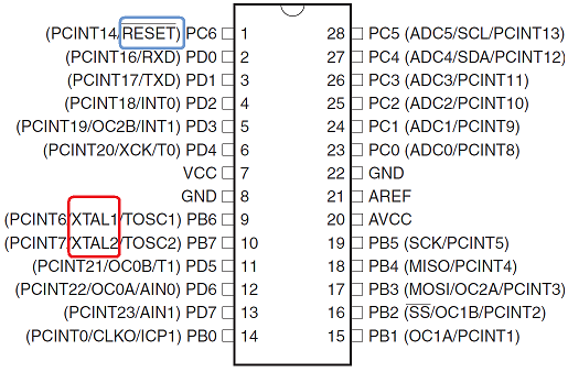
Each Port pin has a secondary function, but only one function can be used at a time.
For example:
- PC6
- The pin PC6 can either work as a General Purpose Input/Output (GPIO) Pin OR as a RESET pin. A reset switch is usually required in an Embedded System. Again from a (beginner level) software developer’s point of view, when the RESET switch is pressed, the C-Language program starts executing (again) from the main() function.
- PB6 and PB7
- The internal oscillator can provide a clock of up to 8MHz to the micro-controller. So it can execute 8 Million Instructions Per Second (MIPS). If it is required to run the microcontroller in a higher speed, an external clock source can be connected to the pins PB6 and PB7. For example usually a crystal of 16MHz (or maximum 20MHz) is connected to these pins.
A crystal oscillator is an electronic oscillator that uses the mechanical resonance of a vibrating crystal of piezoelectric material to create an electrical signal with a very precise frequency. This frequency is used to keep track of time, to provide a stable clock signal for the micro controller. The most common type of piezoelectric resonator used is the quartz crystal.
The picture shows the commonly used Quartz Crystal Oscillator. Note that the oscillating frequency is written on the metal can.
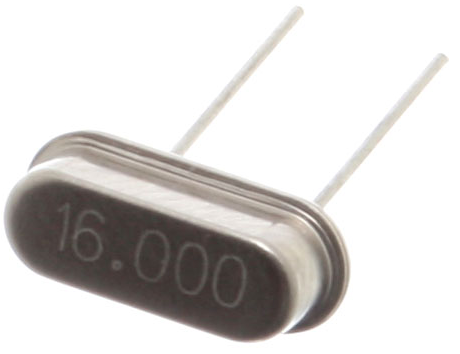

Relative size of a Crystal
Oscillator as compared to the μC
Usually the pins PC6, PB6 & PB7 are used for the above mentioned purposes, now only 23 - 3 = 20pins remain for GPIO.
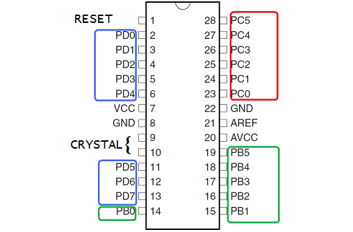
So from now onwards we will consider only 20-pins for GPIO. Usually whenever an advanced function will be required one or more pins from the GPIO will be reduced.
| WR Home Topic Home | Chapter: 1 |
| <Previous | Next> |