| WR Home Topic Home | Chapter: 1 |
| <Previous | Next> |
Chapter 01
Introduction to Persistence of Vision Display Project
Page 1
Definations and Nomenclature
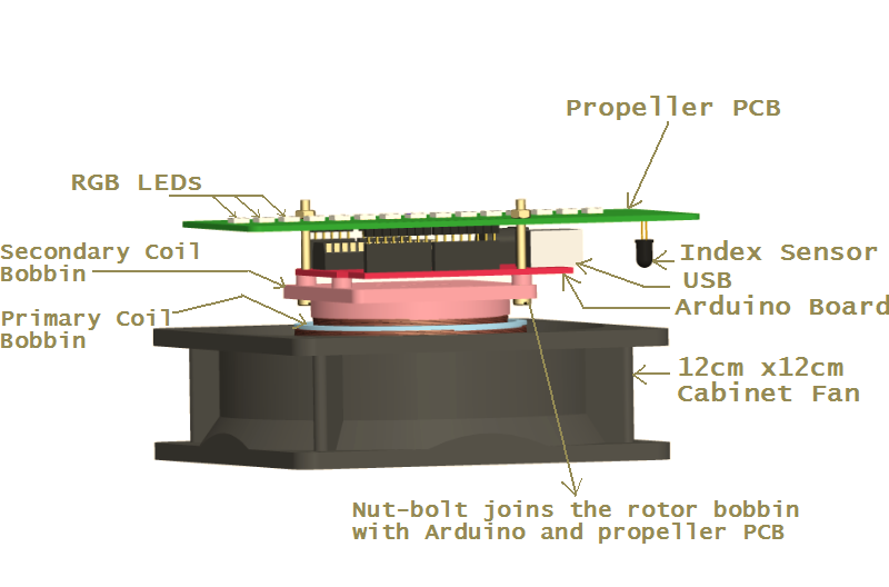
Let's start by examining each part of the POVPD assembly:

There are 3 PCBs involved in the project (only two are shown above):
- The Base PCB on which the 12V DC supply is connected (Remains stationary)
- The Arduino Board (Rotates with Propeller PCB) (shown above)
- The Propeller PCB (shown above)
The rotating Propeller PCB and the Arduino attached to it, needs electric power to operate. How to supply power to something which is rotating? No battery is connected to them, since batteries are heavy and requires re-charging. Slip-rings are NOT used, due to wear-n-tear and sparks. Instead, a rotary transformer is used. Like a simple transformer, it has a primary and a secondary coil. The primary coil remains stationary and the secondary coil is free to rotate with the propeller. Transformers do NOT work on constant DC sources since they need a continuously changing magnetic flux.
"The rate of change of magnetic flux is directly proportional to the induced e.m.f"But, what if the rate of change of flux is zero (like we have a constant 12V DC supply)?
Transformers in general can work on AC or even on Pulsating DC or oscillating voltages. A constant DC power source like 12V power adaptor cannot produce a continuously changing flux on the primary coil and hence no e.m.f can be generated in the secondary coil.
Some circuitry is required, so that the constant DC can be converted to Pulsating DC and then supplied to the primary (stator) coil. The base PCB contains a NE 555 IC based sub-circuit to achieve that.
Also, while experimenting it may be required to change the speed of the rotating propeller. The base PCB contains another NE 555 IC based sub-circuit for the fan-motor speed control.
The Propeller must be aware of its position, when one rotation is completed? So that, switching of LEDs can be controlled w.r.t position. The propeller can determine the index position with the help of a sensor. The base-board (on which the fan motor is mounted) may contain an IR-LED fixed at certain position. The propeller may contain a photodiode. When the photodiode of the rotating propeller passes the IR-LED, some voltage change will occur in photo-diode. In this way the propeller will know that it has reached the index position. If the fan motor is powered and propeller rotates then every time it comes across the IR-LED a pulse is generated in the photodiode. Another method to achieve the above is to use a magnetic field sensor (Hall effect sensor) and a small piece of magnet. In this case the Hall Effect sensor is mounted on the propeller and the magnet is mounted on the base-board. The advantage of using this technique is that IR-LED and its wiring on the base board is not required. But usually the IR-LED and photodiode pair is much cheaper in cost. If the time taken between two pulses is measured and divided by 360° then, its the time required to travel 1°. Similarly the RPM can also be calculated.
Functions of Base PCB:
- Provides pulsating DC to the primary coil
- The RPM of the Propeller can be controlled
- Provides power to the IR-LED (used for index sensing)
Arduino Board
The Arduino Board contains the Micro-controller Atmega328P with 16MHz crystal. The Arduino UNO (or the earlier Arduino Duemilanove) is used for generating patterns based on the propeller position.
Propeller PCB
Functions of Propeller PCB
- To receive induced e.m.f. from secondary coil (of the rotatory transformer), convert it to smooth DC and supply power to Arduino.
- Provide mounting to index sensor and indirectly connect the sensor to Arduino
- Provide mounting to remote-control sensor (TSOP) and indirectly connect the sensor to Arduino
- Provide mounting to RGB LEDs and connect them to Arduino
- Extend the Arduino's RESET switch so that it can be used easily.
- Provide space for connecting supporting components
- Connects to Arduino as an Arduino shield
- Optionally: A Bluetooth Module can be mounted on it !
The Propeller PCB is electrically connected to the secondary coil of the rotatory transformer. The secondary coil has opposite reflections, of the flux changes in primary coil. The induced e.m.f in the secondary (rotor) coil is send to diode bridge on the propeller PCB, which converts it into DC. A smoothening capacitor is also provided. A Zener diode is provided for over-voltage protection.
| WR Home Topic Home | Chapter: 1 |
| <Previous | Next> |