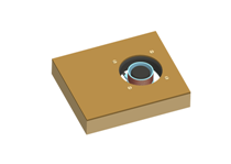
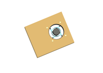
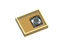
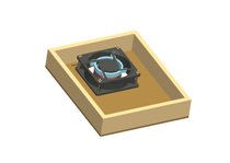
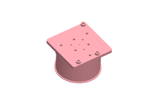
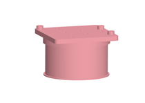
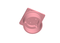
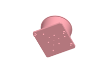
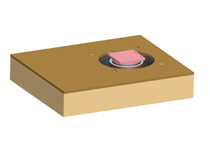
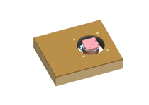
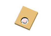
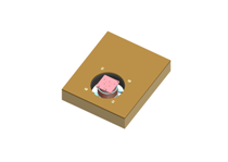
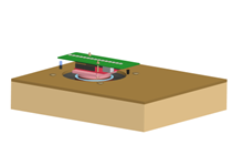
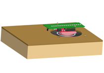
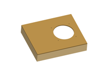
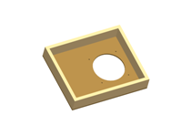
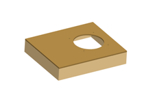
| STEP 1 : Take a wooden board, with wooden frame or an Acrylic sheet |
 |
 |
 |
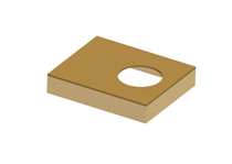 |
| Cut a hole of Φ=11cm |
This will be the chassis |
or the main body |
which holds all parts |
|
|
|
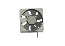
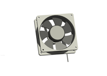
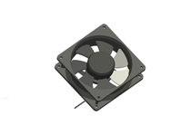
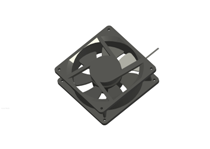
| STEP 2 : Take a cabinet fan 12cm X 12cm size |
|
|
| It has Ball Bearings so its good
|
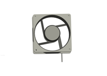
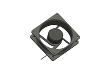
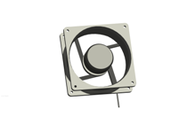
| STEP 3 : Cut the blades of the fan |
 |
 |
 |
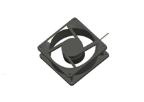 |
| Cut all the blades/fins |
with a cutter |
smoothen the rough cuts |
with file/sandpaper |
|
|
|
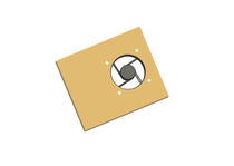
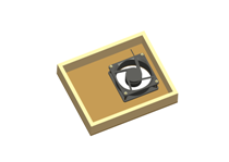
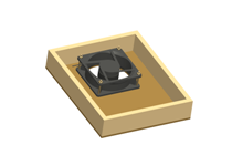
| STEP 4 : Mount it in the board/base-plate |
 |
 |
 |
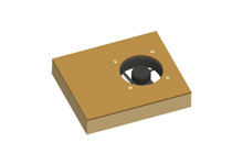 |
| Four nut-bolts |
mounts the fan rotor |
washers can be used |
optionally |
|
|
|
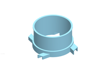
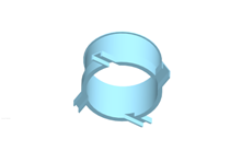
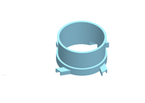
| STEP 5 : Examine the Stator Coil / Primary coil bobbin |
 |
 |
 |
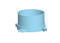 |
| Used to hold |
primary coil |
Mounts on |
fan motor holding "ribs" |
|
|
|
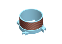
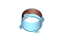
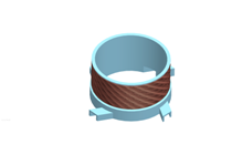
| STEP 6 : Wind the secondary coil 120+120 turns winding. |
 |
 |
 |
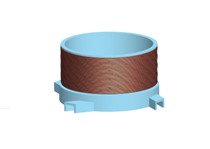 |
| The primary or |
stator winding |
Insulated Copper wire of |
φ=0.29mm or 31-SWG (gauge) |
|
| NOTE: This is a "center tap" winding. It will have 3 terminals. (φ means diameter)
|
| STEP 7 : Mount the stator bobbin on the fan "motor holding ribs" |
|
|
|
|
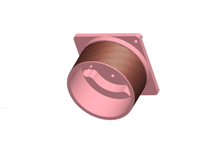
| STEP 8 : Examine the "Rotor Bobbin" |
|
|
|
|
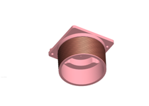
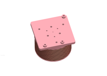
| STEP 9 : Wind the secondary coil on the rotor |
 |
 |
 |
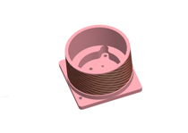 |
| Insulated copper wire |
of approx φ=0.29mm |
or 31-SWG (gauge) |
|
|
| Note: There are two terminals of this (secondary) coil. The winding has 240 turns.
|
| STEP 10 : Insert the "Fan rotor" into the "rotor bobbin" |
|
|
|
|
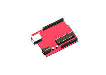
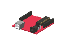
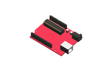
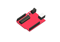
| STEP 11 : Unpack the Arduino board |
|
|
|
|
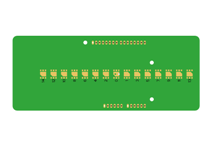
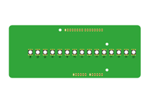
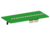
| STEP 12 : Persistence of Vision Propeller Display-PCB (POVPD-PCB) |
 |
 |
 |
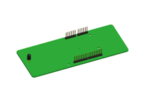 |
| Examine |
Solder the RGB LED's |
Solder all components |
Perform simple testing |
|
|
|
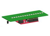
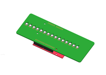
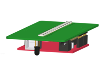
| STEP 13 : Connect the POVPD with Arduino |
 |
 |
 |
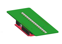 |
| Test it |
Run test programs |
Test Remote Control code |
Test Index sensor code |
|
|
|
| STEP 14 : Mount Arduino to "Rotor Bobbin" with two bolts |
|
|
| NOTE: The 2-wires of the secondary coil are connected to the 2-bolts. Polarity dosen't matters here. Why?
|
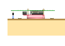
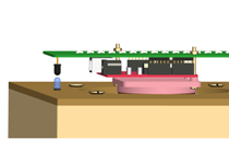
| STEP 15 : Align and properly mount the "index sensing" mechanism |
 |
 |
I3 |
I4 |
| The sensor must be aligned with the source |
The mounting must be firm |
|
|
|
| It may be IR-LED and Photo-diode combination OR a Hall Effect sensor and magnet combination. Using IR-LED and Photo-diode may be more economical.
|
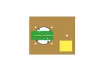
| STEP 16 : Mount the "Base PCB" with the system |
 |
I2 |
I3 |
I4 |
| N1 |
N2 |
N3 |
N4 |
|
NOTE: The Base PCB has two main purpose:
a) To provide Pulsating DC to the primary coil so that e.m.f can be induced in the secondary coil
b) To control the Rotation Per Minute (RPM) of the propellor using Pulse Width Modulation (PWM)
|
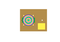
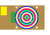
| STEP 17 : Run test programs |
 |
 |
I3 |
I4 |
| Use remote to increase & |
decrease number of glowing LEDs & |
change colours |
|
|
|
|
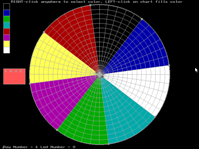
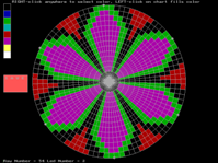
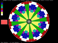
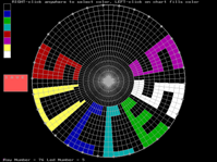
| STEP 18 : Use Graphical User Interface (or develop your own tool) to make display patterns |
 |
 |
 |
 |
| Simple |
Flower |
Pattern |
SUCCESS |
|
| The GUI returns a numerical representation of the "desired-pattern"
|
| STEP 19 : Mixing C-with Assembly code OPTIONAL (Advanced Users only) |
|
|
|
|
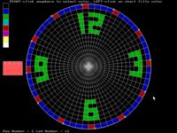
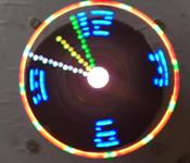
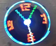
| STEP 20 : Generating dynamic visual patterns: Like the Propeller Clock |
 |
 |
 |
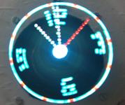 |
| Static Background |
and |
Dynamic Foreground |
|
|
| The dial of the Clock is made using the GUI and the clock-hands are positioned dynamically. Real taste of real time programming !
|


