| WR Home Topic Home | Chapter: 1 2 3 |
| <Previous | Next> |
Chapter 03
Circuitry for the Propeller PCB
Page 7
Some concepts about colours
Previously to get Red colour CC_R was made 0, it seemed like a negative logic. By introducing three "NOT Gates" in the colourCode bits, it will be much easier to imagine about colours. Now to get a Red colour CC_R=1, easy to remember.
NOTE: Though it will introduce an undesired delay. The propagation delay of TTL inverter IC, let us say 22ns (worst: 10-micro second depending on selection of IC) We will have to deal with it later.

Using three LEDs (R, G, B) and two states (ON, OFF):
2 states raise to 3LEDs = 8 colour combinations can be made
( 2^3 = 8 )
Example If Red and Blue LEDs are glowing nearby, they will produce a visual effect of Magenta color. The IC manufacturers, house the three LEDs in the same package.
THE RGB LED
The following picture shows a RGB LED.
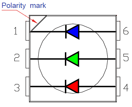
NOTE: The polarity mark differ for LEDs of different models, manufacturers. It may NOT always indicate a cathode for Blue LED. Please consult the datasheet of the LED or test it practically with the multi-meter. The continuity/diode-testing mode can be used to test the LED for polarity. It applies a very small voltage to the LED and it starts glowing if the probes at placed in the right polarity.
| 0 | BLACK | All OFF |  |
 |
| 1 | BLUE |  |
 |
|
| 2 | GREEN |  |
 |
|
| 3 | CYAN | (G + B) |  |
 |
| 4 | RED |  |
 |
|
| 5 | MAGENTA | (B+ R) |  |
 |
| 6 | YELLOW | (G+ R) |  |
 |
| 7 | (R+ G+ B) |  |
 |
colorChart for BGR:
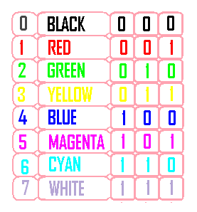
Difference between RGB and BGR colourCode:
|
|
| WR Home Topic Home | Chapter: 1 2 3 |
| <Previous | Next> |