| WR Home Topic Home | Chapter: 1 2 3 |
| <Previous | Next> |
Chapter 03
Circuitry for the Propeller PCB
Page 10
ULN 2003
OVER SIMPLIFIED
There is some difference between logical understanding and practical realization of the LED switching circuit. There are three colour control bits. (Which we called as master-control or common-cathode, CC_R, CC_G, CC_B) The three colour control bits will be outputted by three output pins. Each output pin will be responsible to provide common cathode for onSequence of 15 LEDs.
Example: If all 15 RED LEDs are to be switched ON, the single output pin acting as CC_R will source a lot of electrons, for all 15 RED LEDs.
Since it will be difficult for a single micro-controller pin to source electrons for all 15 LEDs, we use a transistor to drive the LEDs.
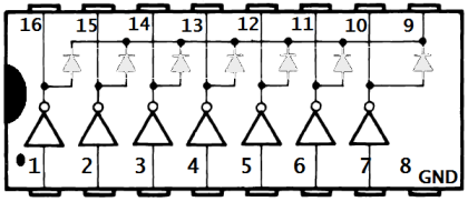
We call these transistors are drivers. Set of 7-drivers (which also "inverts" like NOT gates), are available in a single IC package ULN2003A. We may only use 3 out of 7-drivers.
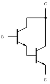
We use a "Darlington-pair transistor" to drive each of the three common cathodes. The Darlington-pair is a structure consisting of two transistors connected in such a way that the current amplified by the first transistor is amplified further by the second one. This configuration gives a much higher current gain than each transistor taken separately.

The ULN2003A devices are high-voltage, high-current, Darlington transistor arrays. Each consists of seven NPN Darlington pairs.
The output current rating of a single Darlington pair is 500 mA. (The Darlington pairs can be paralleled if much higher current capability is required).
Typical applications of ULN2003, include relay drivers, hammer drivers, lamp drivers, display drivers (LED and gas discharge) and line drivers.
The micro controller in Arduino UNO R3 is Atmega328P. The datasheet of Atmega328P says: The pin driver is strong enough to drive LED displays directly. It also says, Absolute Maximum Ratings (NOT Recommended Maximum Ratings) of for Atmega328P, DC Current per I/O Pin is 40mA. So it is better use a driver, instead of taking a risk.
Some excerpt from data sheet:
1] The sum of all IOH, for ports C0 - C5, D0- D4, ADC7, RESET should not exceed 150mA.
2] The sum of all IOH, for ports B0 - B5, D5 - D7, ADC6, XTAL1, XTAL2 should not exceed 150mA.

1] The sum of all IOL, for ports C0 - C5, ADC7, ADC6 should not exceed 100 mA.
2] The sum of all IOL, for ports B0 - B5, D5 - D7, XTAL1, XTAL2 should not exceed 100 mA.
3] The sum of all IOL, for ports D0 - D4, RESET should not exceed 100 mA.
Please click here for some more details. Though it is recommended to study the data sheet from Atmel® website.
ULN 2003A
There are 7-inputs and 7-outputs:
Pin 1 input, Pin 16 output
Pin 2 input, Pin 15 output
Pin 3 input, Pin 14 output
Pin 4 input, Pin 13 output
Pin 5 input, Pin 12 output
Pin 6 input, Pin 11 output
Pin 7 input, Pin 10 output
Pin 8 is GND and Pin 9 is connected to +5V

Example 1 :
INPUT : If Pin 1 is connected to Logic-1
Output: Pin 16 will be Logic-0. (NOTE: Its inverted as compared with input)

Example 2 :
INPUT : If Pin 1 is connected to Logic-0
Output: Pin 16 will behave like its not connected to anything (N/C).

Similarly ...
Example 3 :
INPUT : If Pin 2 is connected to Logic-1
Output: Pin 15 will be Logic-0. (NOTE: Its inverted as compared with input)

Example 4 :
INPUT : If Pin 2 is connected to Logic-0
Output: Pin 15 will behave like its not connected to anything (N/C).

And so on till Pin-7 ......
| WR Home Topic Home | Chapter: 1 2 3 |
| <Previous | Next> |