| WR Home Topic Home | Chapter: 1 2 3 |
| <Previous | Next> |
Chapter 03
Circuitry for the Propeller PCB
Page 11
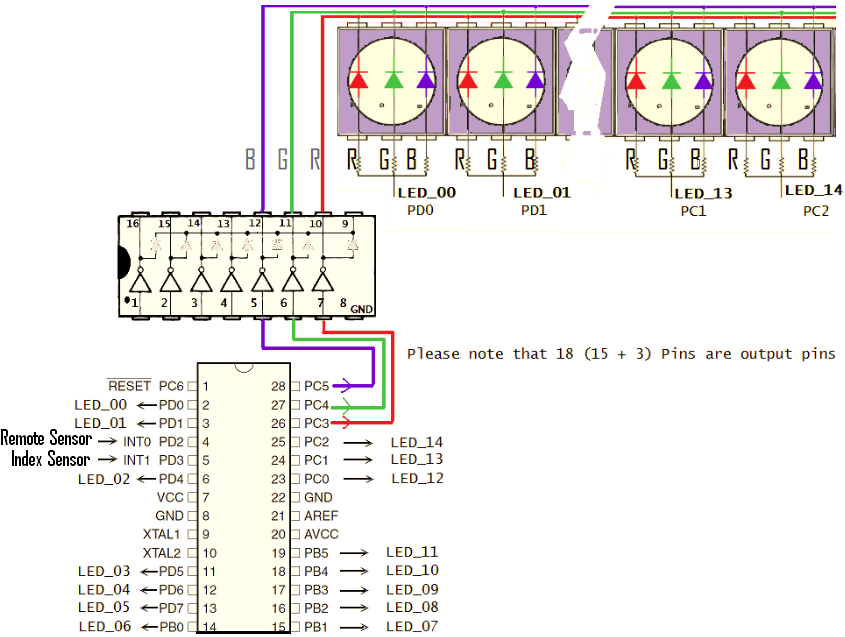
So, Considering the circuit, it is clear that
INPUT PINs
PD2 TSOP_INPUT (Remote Sensor Input)
PD3 INDEX_SENSOR_INPUT

OUTPUT PINS
PD0 LED_00
PD1 LED_01
PD4 LED_02
PD5 LED_03
PD6 LED_04
PD7 LED_05
PB0 LED_06
PB1 LED_07
PB2 LED_08
PB3 LED_09
PB4 LED_10
PB5 LED_11
PC0 LED_12
PC1 LED_13
PC2 LED_14

PC3 LED_RED_COMMON
PC4 LED_GREEN_COMMON
PC5 LED_BLUE_COMMON
The next chapter explains some programming examples
| WR Home Topic Home | Chapter: 1 2 3 |
| <Previous | Next> |