| WR Home Topic Home | Chapter: 1 2 3 4 5 6 7 8 |
| <Previous | Next> |
Chapter 08
Developing an algorithm to generate simple (static) visual patterns
Page 1
Experiment 1
STEP 1: Represent the PATTERN in numeric format
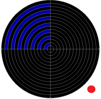
In other words: Initialize the array(s) !Suppose the following pattern is to be displayed on the rotating propeller:
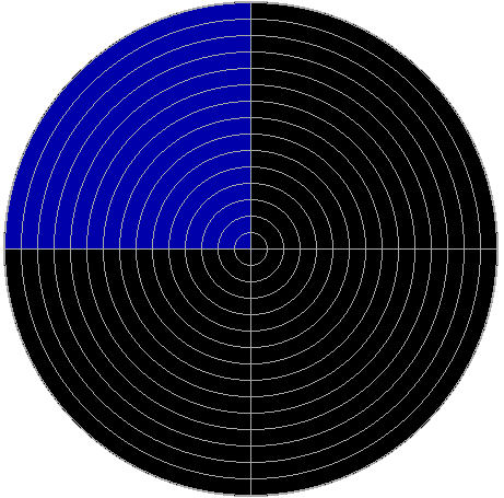
It can be seen that only the first quadrant is lit-up with Blue color. The remaining three quadrants are not glowing.
In order to do the calculations, lets develop some terminology.
The first parameter is NUMBER_OF_LEDS and its value is 15 (from 0th-LED to the 14th-LED)
LED number 0,2,4,6,8,10,12 and 14 are even LEDs and
the remaining are ODD LEDs.
The next parameter is GUI_RAY_RESOLUTION
If the circular area formed by rotation of the propeller is divided in 4 parts then we will say that the resolution is 4. Since a Graphical User Interface (GUI) is used, it is termed as GUI_RAY_RESOLUTION.
RAY: Each of the 4-parts (or a pie slice) is called a ray.
For example, the ray resolution of the above screen shot is 4, then there are 4-rays
The above 4-ray pattern can be denoted by:
 4  4  4  4  4  4  4  4  4  4  4  4  4  4  4 -  ray_no= 0
 0  0  0  0  0  0  0  0  0  0  0  0  0  0  0 -  ray_no= 1
 0  0  0  0  0  0  0  0  0  0  0  0  0  0  0 -  ray_no= 2
 0  0  0  0  0  0  0  0  0  0  0  0  0  0  0 -  ray_no= 3
Here 4 stands for the color code BLUE and 0 stands for LED OFF (BLACK)
and 4 is repeated 15 times to denote color of 15 LEDs. All the 15 LEDs of ray_no = 0 are BLUE (color code = 4).
The leftmost 4 stands for the LED_13 which is ODD and the outermost LED (nearest to outer edge)
The rightmost 4 stands for the LED_0 which is EVEN and the innermost LED (nearest to center)
SECTOR: There are 15 x 4 = 60 sectors in the diagram.
STEP 2: SWAP: ODD sectors of OPPOSITE rays
It should be noted that all 15 LEDs are not on one side of the propeller. Half the LEDs (Even number LEDs) are on one side of the center of propeller and
the other half (Odd LEDs) are on the other. In other words the odd and even LEDs have an exact phase difference of 180 degrees.
If it is provided that GUI_RAY_RESOLUTION ( total number of rays in 360 degree) will always be an even number then each pie slice (ray) will have some other pie slice exactly opposite to it. Each ray will have and opposite ray.
For example the Ray 0 is opposite to Ray 2 and
For example the Ray 1 is opposite to Ray 3
Also note that the total time consumed in one rotation is equally divided in 4 rays
Since there are only 4 rays the TPR (Time Per Round) is divided by 4
ray_no= 0 consumes one forth TPR
ray_no= 1 consumes next one forth TPR
ray_no= 2 consumes next one forth TPR
ray_no= 3 consumes next one forth TPR
Also note that the propeller is divided into two parts from its center. The first half of the propeller has EVEN LEDs and the second half has the ODD LEDs. At a given time instant if the EVEN LEDs are in the area of ray_no=0 then the remaining half of the propeller is in the area of ray_no=2. In this way, it can be said that the propeller covers two rays at the same time instant. It is also concluded that EVEN and ODD LEDs are in opposite ray areas at the same time instant.
Let’s name the two sides of the propeller as HEAD and TAIL
In the diagrams the Head will be denoted by a RED dot
Note the Head of the propeller in the animation
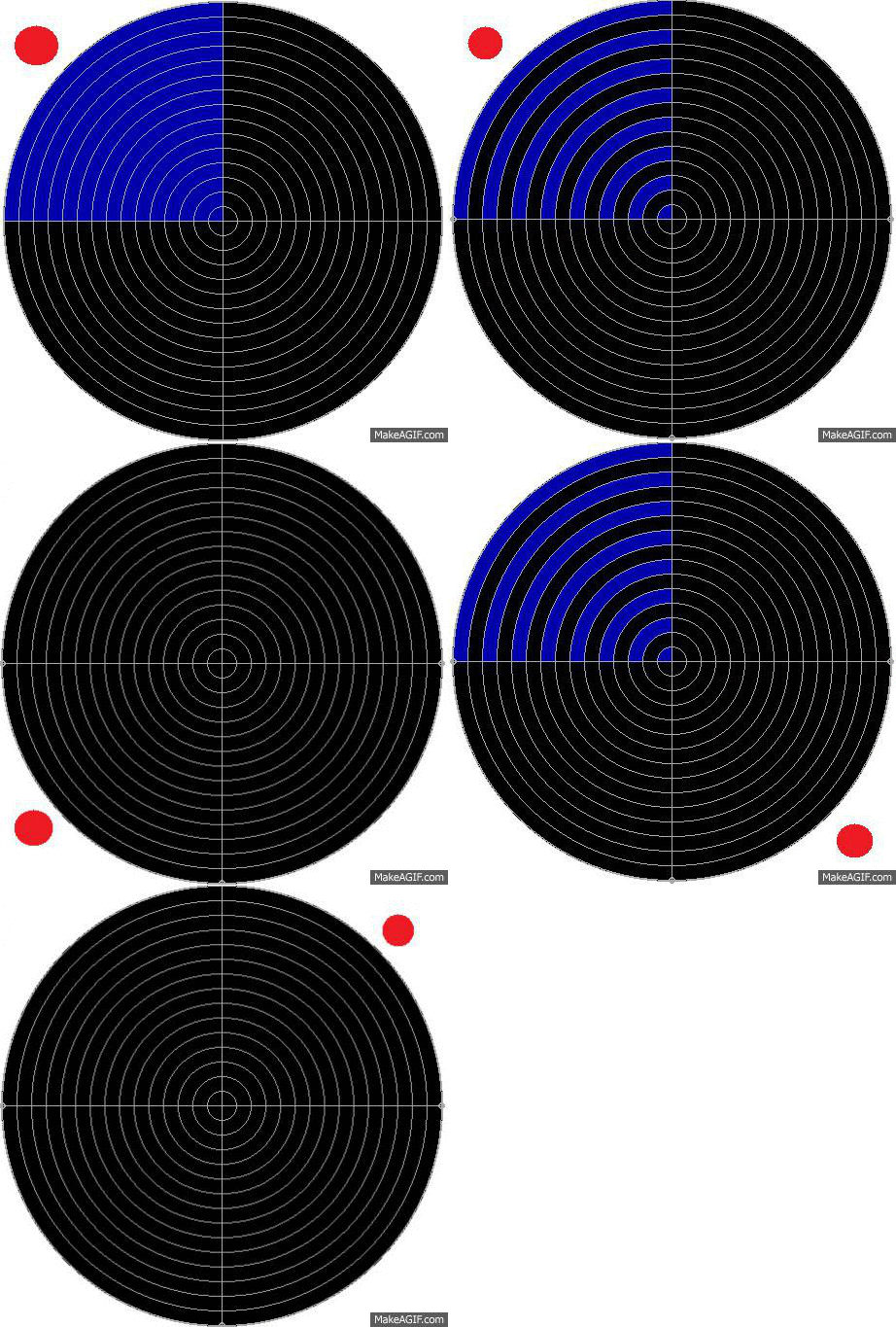
In order to display the desired pattern, consider the following figures.
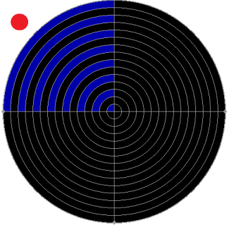
Glow the EVEN LEDs when the propeller’s head is in First Quadrant and
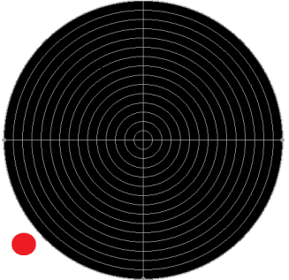
Glow the ODD LEDs when the propeller’s head is in the Third Quadrant
 |
 |
| Glow the EVEN LEDs when the propeller’s head is in 1st Quad |
Glow NO LEDs when the propeller’s head is in 2nd Quad |
 |
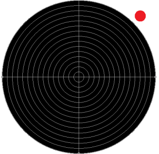 |
| Glow the ODD LEDs when the propeller’s head is in 3rd Quad |
Glow NO LEDs when the propeller’s head is in 4th Quad |
In this way the opposite rays acts as "PARTNER" rays if a solid color pattern is to be formed, as seen in the above case. Now consider the following sequence:
SWAP: Odd sectors of opposite rays
| 0 | 4 | 0 | 4 | 0 | 4 | 0 | 4 | 0 | 4 | 0 | 4 | 0 | 4 | 0 | ray_no=0 |
| 0 | 0 | 0 | 0 | 0 | 0 | 0 | 0 | 0 | 0 | 0 | 0 | 0 | 0 | 0 | ray_no=1 |
| 4 | 0 | 4 | 0 | 4 | 0 | 4 | 0 | 4 | 0 | 4 | 0 | 4 | 0 | 4 | ray_no=2 |
| 0 | 0 | 0 | 0 | 0 | 0 | 0 | 0 | 0 | 0 | 0 | 0 | 0 | 0 | 0 | ray_no=3 |
STEP 3: Convert in 16-bit format
Since there are 15 LEDs and the information is to be stored in a 16-bit variable (unsigned int)
The above display information can be written in 16 bit format as:
ray_no= 0
0  .  4  .  4  .  4  .  4  .  4  .  4  .  4  .  BLUE    ( 4)
An extra zero is padded to the MSB, to make it count 16
The above can be written in 16-bit as: 0x2AAA or Binary=0010 1010 1010 1010  Color= BLUE    ( 4)


 ray_no= 1

 All LEDs OFF for ray : 0x0000 or Binary=0000 0000 0000 0000  BLACK   ( 0)


 ray_no= 2
0 4  .  4  .  4  .  4  .  4  .  4  .  4  .  4  BLUE    ( 4)
An extra zero is padded to the MSB, to make it count 16
The above can be written in 16-bit as: 0x5555 or Binary=0101 0101 0101 0101  Color= BLUE    ( 4)


 ray_no= 3

 All LEDs OFF for ray : 0x0000 0000 0000 0000 0000  BLACK   ( 0)
 PORTC=0X00 PORTB=0X00 PORTD=0X00 or Binary= 0000 0000  | 0000 0000  | 0000 0000
STEP 4: Convert to PORT OUTPUT format
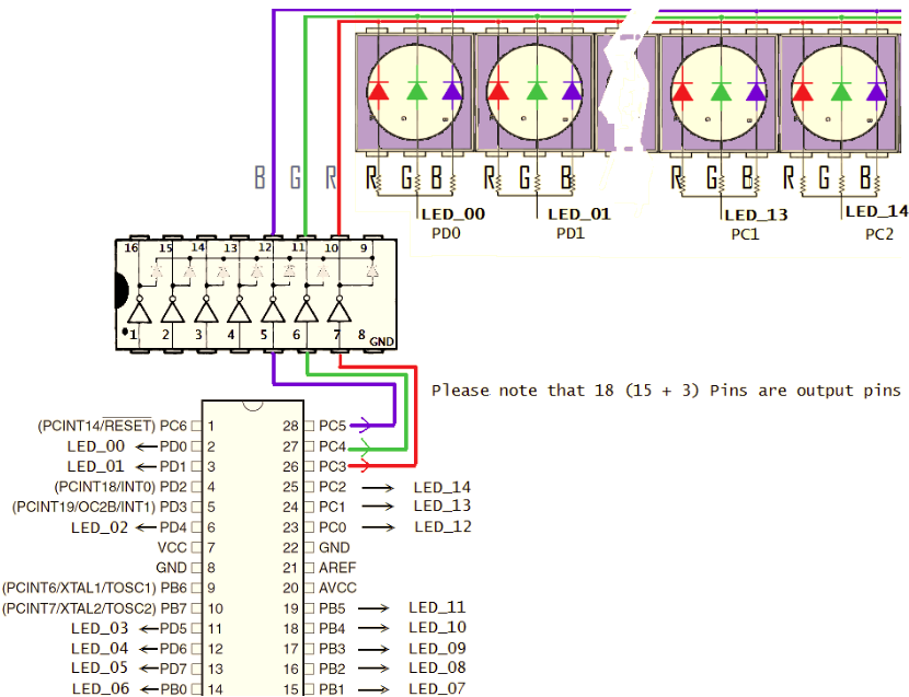
Remember How the LEDs are connected to the three ports:
The 16-bit ON/OFF Sequence is to be distributed among THREE ports:
NA FOR:PORTC FOR:PORTB FOR:PORTD
__ ___|____ ________|________ ________|________
15= 14_13_12=11_10_09_08_07_06= 05_04_03_02_01_00
Also re-call that which port-pins are connected to which LED
// PORTD pins of interest (pins on which LEDs are connected)
// LED_05 LED_04 LED_03 LED_02 LED_01 LED_00
//    PD7    PD6    PD5    PD4    PD1    PD0


// PORTB pins of interest (pins on which LEDs are connected)
// LED_11 LED_10 LED_09 LED_08 LED_07 LED_06
//    PB5    PB4    PB3    PB2    PB1    PB0


// PORTC pins of interest (pins on which LEDs are connected)
// LED_14 LED_13 LED_12
//    PC2    PC1    PC0


// Common Cathode for all RED   LEDs is connected to PC3
// Common Cathode for all GREEN LEDs is connected to PC4
// Common Cathode for all BLUE  LEDs is connected to PC5
//  B   G   R
// PC5 PC4 PC3     COLOR       DECIMAL
//   0   0   0     BLACK          0
//   0   0   1     RED            1
//   0   1   0     GREEN          2
//   0   1   1     YELLOW         3
//   1   0   0     BLUE           4
//   1   0   1     MAGENTA        5
//   1   1   0     CYAN           6
//   1   1   1     WHITE          7

// So PORTC pins of interest for controlling RAY-color are
// PC5 PC4 PC3
In this way the byte sequence for the 3 ports, for the 4 quadrants can be written as:
 PORTC=0X22 PORTB=0X2a PORTD=0Xa2      0010 0010  | 0010 1010  | 1010 0010
 PORTC=0X00 PORTB=0X00 PORTD=0X00      0000 0000  | 0000 0000  | 0000 0000
 PORTC=0X25 PORTB=0X15 PORTD=0X51      0010 0101  | 0001 0101  | 0101 0001
 PORTC=0X00 PORTB=0X00 PORTD=0X00      0000 0000  | 0000 0000  | 0000 0000
STEP 5: Consider the following program
Suppose if the Propeller is rotating at a constant speed of RPM = 1200
 It will make 20 number of turns in a second and to move one degree it will take 137.888889  micro seconds
Assume that time taken to execute the instructions is negligible.
What pattern the following code displays/renders:

D = 137.888889;
while(1)
{
    // First
	PORTC=0X22;
	PORTB=0X2a;
	PORTD=0Xa2;

	for(i=0; i<90; i++)
		delay(D); // exact delay in micro seconds

    // Second
	PORTC=0X00;
	PORTB=0X00;
	PORTD=0X00;

	for(i=0; i<90; i++)
		delay(D); // exact delay in micro seconds

    // Third
	PORTC=0X25;
	PORTB=0X15;
	PORTD=0X51;

	for(i=0; i<90; i++)
		delay(D); // exact delay in micro seconds

    // Forth
	PORTC=0X00;
	PORTB=0X00;
	PORTD=0X00;

	for(i=0; i<; i++)
		delay(D); // exact delay in micro seconds
}
The first quadrant of the circular area formed by the rotating propeller will display ? Color
The second quadrant of the circular area formed by the rotating propeller will display ? Color
The third quadrant of the circular area formed by the rotating propeller will display ? Color
The forth quadrant of the circular area formed by the rotating propeller will display ? Color
NOTE: Port pins should not be addressed directly to send outputs (For example PORTD=0xa2) because other input devices (such as remote sensor TSOP and Index Sensor ) are connected to the port. The above code is just a diluted version to help and understand the development of the algorithm.
| WR Home Topic Home | Chapter: 1 2 3 4 5 6 7 8 |
| <Previous | Next> |