| WR Home Topic Home | Chapter: 1 2 3 4 5 6 7 8 9 10 11 12 13 |
| <Previous | Next> |
Chapter 13
Page 7
STEP: Primary winding or stator winding of the rotatory transformer
- Find the diameter of the rotor developed in previous step.
- Take a plastic rod which is 6mm thicker in diameter (hair-oil bottels or deodorant bottels can be used)
- Take thin plastic film/sheet (OHP sheet can be easily found) and roll it on the plastic rod. Put some adhesive tape on it, so that it does not unwinds.
- Wind 120 turns of the insulated copper-wire. (0.3mm diameter)
(Please click on an image to enlarge)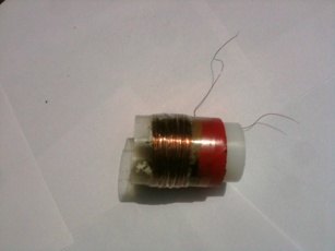
- Put some adhesive tape on the coil, so that it does not unwinds. But too much tape is not good as coil may be heated sometimes. A good design of rototary transformer will not let it heat. So it all depends on the design. The versions developed later have efficient designs, the coils do not heat even when operated for 6-hours continuously.
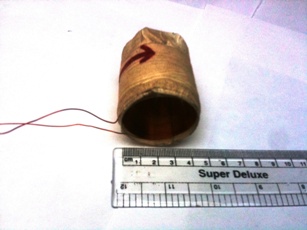
- Both windings are now ready. Insert rotor coil into stator coil and see that it goes smoothly.
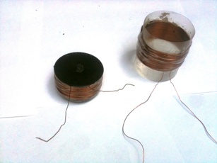
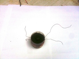
- Since the rotor is to be placed back on the fan armature, it must not contain anything which restricts its rotory motion. Make it smooth.
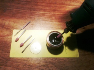
- Remove the transparent insulation. The insulation may be burned and the carbon can be removed with a blade.
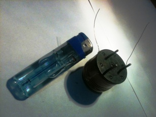
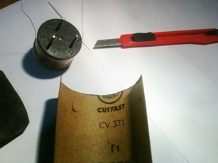
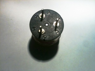
- Connect the two ends of the copper wire to the bolts mounted in the fan rotor.
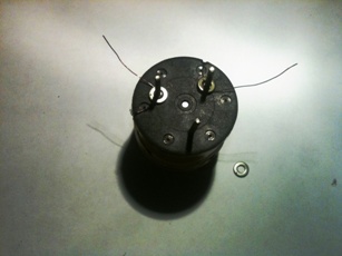
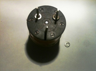
- The third bolt is not connected.
- TESTING: The multimeter is configured to continuity testing mode (beep-sign). The two bolts on which the copper wire was connected must show continuity. The resistance is approximately 7 Ω (ohm).
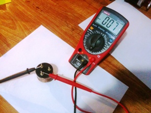
In this way the rototary transformer is ready.
| WR Home Topic Home | Chapter: 1 2 3 4 5 6 7 8 9 10 11 12 13 |
| <Previous | Next> |