| WR Home Topic Home | Chapter: 1 2 3 4 5 6 7 8 9 10 11 12 13 |
| <Previous | Next> |
Chapter 13
Page 9
Development of Propeller PCB
- Take a general purpose PCB which is commonly available for developing IC based circuits.
(Please click on an image to enlarge)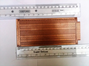
- If you are using an Arduino Compatible board made by third-party then make sure you check the connector type. Is it male-type od female type?
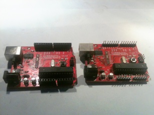
- Take some time for planning
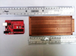
- Select appropriate connector: Male Berg Connector (Single row pin header)
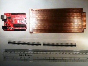
- Cut the connector into groups, depending on Arduino pin grouppings
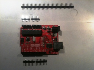
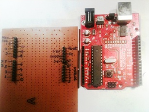
- Insert the connector-pins in Arduino and place it on general purpose PCB. Note that the USB connector is on the side of the PCB and not in the middle. Keeping the USB and Power connectors in side will be better, as they will be used with cables multiple times.
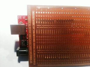
- The connector is ready for soldering now
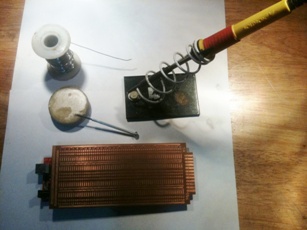
- Apply soldering flux else there will be dry-soldering and loose connections. Remember it will be rotating at high speed. Loose connections may rest the Arduino multiple times OR cause other problems.
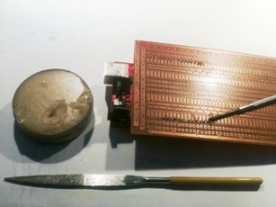
- Solder all the pins.
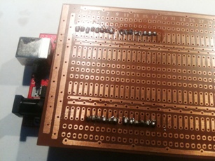
- Remove the Arduino board (straight upwards)
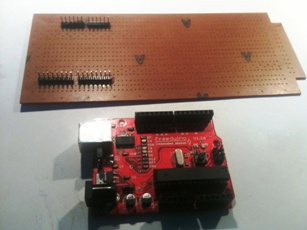
- It will look like
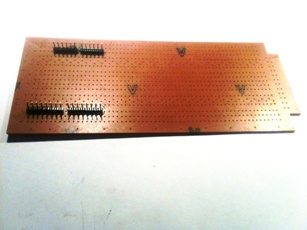
- Name the pins by juxtaposing the Arduino with PCB
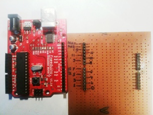
- Name the pins by juxtaposing the Arduino with PCB
| WR Home Topic Home | Chapter: 1 2 3 4 5 6 7 8 9 10 11 12 13 |
| <Previous | Next> |