| WR Home Topic Home | Chapter: 1 2 3 4 5 6 7 8 9 10 11 12 13 |
| <Previous | Next> |
Chapter 13
Page 11
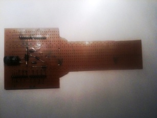
- Add a 4-diode bridge and a Zener diode to the propeller PCB
(Please click on an image to enlarge)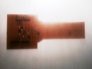
- There are three mounting points where the Propeller PCB will be mounted to the Rotor bobbin. Two of them are connected to the coil. These two points bring the induced e.m.f from the coil to the inputs of the 4-diode bridge. The zener diode is for over-voltage protection
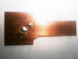
- The output of the 4-diode bridge is connected to Arduino. The positive terminal of the bridge output is connected to Arduinos V_IN pin in the power-pin-group. The ground connects to ground.
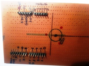
- The terminal connection pads must be properly made
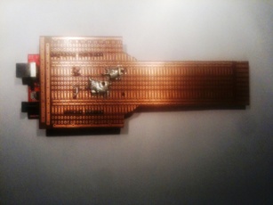
- Add a capacitor for smoothinmg the DC
| WR Home Topic Home | Chapter: 1 2 3 4 5 6 7 8 9 10 11 12 13 |
| <Previous | Next> |