| WR Home Topic Home | Chapter: 1 2 3 4 5 6 7 8 9 10 11 12 13 |
| <Previous | Next> |
Chapter 13
Page 13
Soldering RGB LEDs
(Please click on an image to enlarge)
- A separate resistance should be used for Red, Ggeen and the Blue LED.
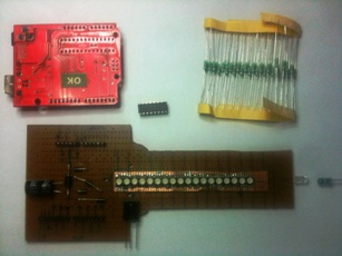
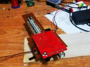
- Mount the LED PCB on the Propeller PCB, such that the first LED consides with center of rotation.
- Connect all Red-Cathodes together, connect all green-cathodes together, connect all-blue cathodes together.
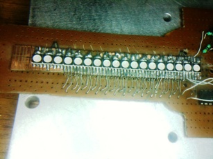
- Using a convex lense (magnifying glass) verify that there are no short-circuits
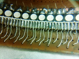
- For this experimental propeller 18 LEDs were soldered but only 15 of them were connected, 3 remained extra
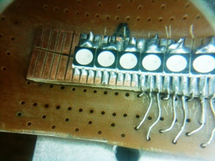
- Extra LEDs
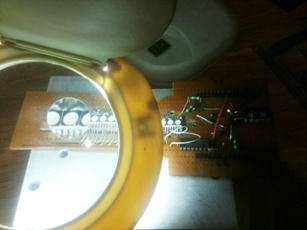
- Three common cathods are formed. One cathode for each of R, G, and B
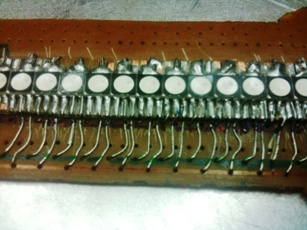
- As a short-cut anodes of each LED were sorted and a single resistance was attached to each anode group. So there were 15 anode groups and 15 resistances were connected. In order to produce all 7-color-shades properly anode of each R,G,B must be connected to a seperate resistance. The other end of the 3-resistances can be joined together. In total there should be 45-resistances (15 x 3).
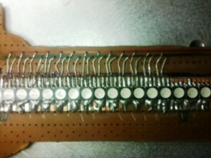
- Connect 15 SMD resistances ( 470 Ω each)
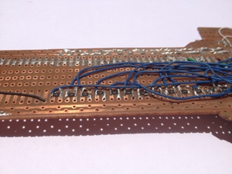
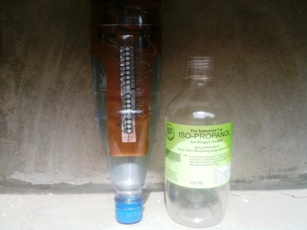
- Wash with ISP-propanol to clean the Propeller PCB
- Each LED can be tested without using the Arduino board
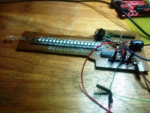
- Each LED can be tested without using the Arduino board
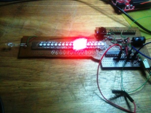
- Using the Arduino board test the LEDs
| WR Home Topic Home | Chapter: 1 2 3 4 5 6 7 8 9 10 11 12 13 |
| <Previous | Next> |