| WR Home Topic Home | Chapter: 1 2 3 4 5 6 7 8 9 10 11 12 13 |
| <Previous | Next> |
Chapter 13
Page 15
Power up the propeller
Induce voltage in secondary coil- Provide PWM to primary coil: In order to induce e.m.f. in the secondary coil, the primary coil's magnetic flux must change. Hence the primary coil was connected to a microcontroller based circuit which could provide it PWM. The microcontroller was Atmega32 and was connected to L298 driver ICs. (The kit saves money by using NE555 IC instead of microcontroller and generates square wave).
(Please click on an image to enlarge)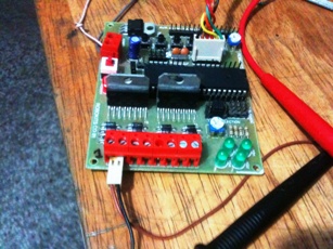
- Check voltage at secondary coil: The multimeter was configured for AC voltage measurement ranging from 0 - 20 V AC and was connected to the secondary coil.
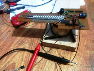
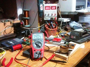
- Depending on the winding ratio of primary and secondary coil and a number of other factors, voltage was induced in the secondary coil. The propeller can now get wireless power supply! 12Volt was given to primary coil and 14.05Volt was generated in the secondary coil. It can be seen that the primary circuit consumed 550mA of current.
- The Fan motor was powered
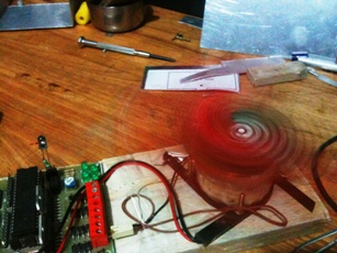
- A program was flashed in Arduino to turn ON lights in different colors. It should be noted that : If three LEDs can have ON-OFF states then 2^3 = 8 colors can be formed. When all LEDs are off black is formed so removing this case we have 7 possiblities. Out of these 7 only 4 can be acheived, Why? Because we took a shortcut. Remember the common resistance for all anodes of the same LED instead of using three (or using 15 instead of 45 resistances). Any color shade which involves RED turns to RED-only as RED LED consumes all current and none is left for the other LED.
Example : Magenta color requires RED + BLUE, when RED and BLUE segments of the same RGB LED are powered, then the RED LED consumes all the current and none is left for BLUE LED, so only RED glows. Hence instead of Magenta we can only see RED color. The solution is simple use 45 resistances instead of just 15 resistances. Since CYAN color (GREEN + BLUE) does not require RED LED it is still visible, but for perfect CYAN color GREEN and BLUE LEDs must have their own resistances.
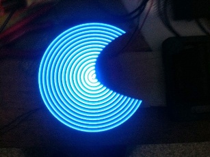
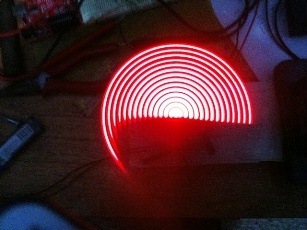
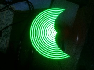
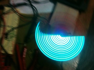
NOTE: Camera cannot be fooled easily by presistence of vision, it all depends on its shutter speed. The circles in the images were all full circles but camera cant pick it as a circle. The shutter speed must be slow to capture the full circle. So all images further will have this incompleteness.
Till now there was no use of index sensor.
| WR Home Topic Home | Chapter: 1 2 3 4 5 6 7 8 9 10 11 12 13 |
| <Previous | Next> |