| WR Home Topic Home | Chapter: 1 2 |
| <Previous | Next> |
Chapter 02
Basics of Animation and Forward Kinematics
Page 1
(Part-II: MATLAB® Programming Tutorials: Robot Control and Mathematics)
This chapter covers the following topics:- Drawing the two links
- Animating in a Figure Window : A Growing Plant
- Developing a Function for Rotation Transformation: Forward Kinematics
- Animation of Rotating Arm
The following variables are used:
L1 and L2 are the link lengths and should be treated as constants. They will be changed only if the mechanical structure of the robot is changed.
L1 = 110.0; % Link Length in mm
L2 = 140.0; % Link Length in mm
Consider a two link mechanism it will have three points:
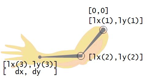
lx(1), ly(1) This point will always conside with the Origin (0,0).
The motor M1 can rotate this point along the z-axis.
lx(2), ly(2) This is the junction point of Link-1 and Link-2
The motor M2 can rotate this point along the z-axis.
lx(3), ly(3) This is the tip of the robot's gripper.
Destination point (dx,dy) is the point, where the robot needs to reach in order to acomplish a certain task. When the robotic arm is moved accordingly the the tip of the gripper [lx(3), ly(3)] will conside with (dx, dy).
The distance between the Point [lx(1), ly(1)] and the Point [lx(2), ly(2)] will always be L1
The distance between the Point [lx(2), ly(2)] and the Point [lx(3), ly(3)] will always be L2
The distance between the Point [lx(1), ly(1)] and the Point [lx(3), ly(3)] will always be < = SUM_L1_L2
SUM_L1_L2 is the sum of L1 and L2
| WR Home Topic Home | Chapter: 1 2 |
| <Previous | Next> |