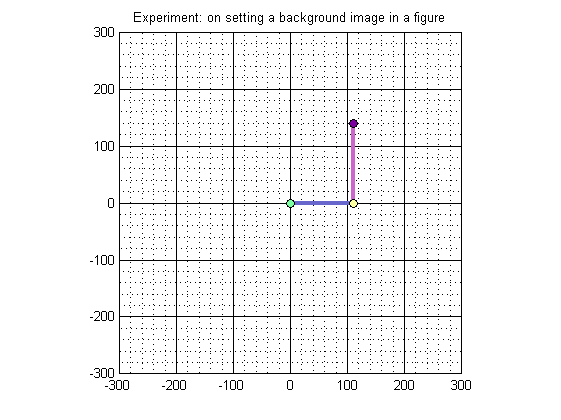
close all; clear; clc;
global debugLevel_01;
global L1;
global L2;
global SUM_L1_L2;

debugLevel_01 = 1;

L1 = 110.0; % Link_1 Length in mm
L2 = 140.0; % Link_2 Length in mm
SUM_L1_L2 = L1 + L2;

initalizeArmCoordinates;
printArmCoordinates;

hf = figure('color','white');
% maximize(hf);
axis equal

maximum_x_limit =   ceil(SUM_L1_L2/100)*100;
maximum_y_limit =   ceil(SUM_L1_L2/100)*100;
minimum_x_limit = - ceil(SUM_L1_L2/100)*100;
minimum_y_limit = - ceil(SUM_L1_L2/100)*100;

% % % %  Experiment: 1
% % % % Run the code. Let all Experiment(s) be commented
% % % % Observe that Y increses 'Upwards', just like in Cartesian Co-ordinate
% % % % System.

% % % %  Experiment: 2
% % % %  To display the background image, read the images and show it
% % % %  U N C O M M E N T :
%          bk_image = imread('background_c.bmp');  % Read the image in an array
%          image(bk_image);                        % display it on the screen
% % % %
% % % %  NOTES on  Experiment: 2
% % % %  PROBLEM 1: As soon as a background image is diaplayed, Y increase 'Downwards'
% % % %  unlike the Cartesian Co-ordinate System. This is because, in an image
% % % %  (or in computer graphics)Y-axis
% % % %  increases downwards! Also note that the robot arm looks reversed
% % % %  PROBLEM 2: Only a portion of image is displayed due to the axis
% % % %  limits set previously.


% % % %  Experiment: 3
% % % %  Comment previous Experiment and uncomment this Experiment
% % % %  Problem 2 is solved here: use imagesc instead of image
%            bk_image = imread('background_c.bmp');
%            imagesc(minimum_x_limit, minimum_y_limit, bk_image);
% % % %    % The above can can also be written as:
% % % %    % imagesc([minimum_x_limit, maximum_x_limit], [minimum_y_limit, maximum_y_limit], bk_image);


% % % %  Experiment: 4
% % % %  Comment previous Experiment and uncomment this Experiment
% % % %  Problem 1 is solved here: Change y-axis direction to normal
%             bk_image = imread('background_c.bmp');
%             imagesc([minimum_x_limit, maximum_x_limit], [minimum_y_limit, maximum_y_limit], bk_image);
%             set(gca,'ydir','normal');  % set the y-axis back to normal.
% % % %  PROBLEM 3: But the above solution introduces a new problem!
% % % %             The image gets inverted (and Robot arm gets normal)
% % % %
% % % %  SOLUTION HINT: After all the image is stored in an array named
% % % %                 'bk_image' so why not 'flip' this array upside-down
% % % %                 By using the functions like:
% % % %                 fliplr, flipud, permute, rot90 and flipdim


% % % %  Experiment: 5
% % % %  Comment previous Experiment and uncomment this Experiment
% % % %  Problem 3 is solved here: By using flipdim(I,1)
%             bk_image = imread('background_c.bmp');
%             bk_image = flipdim(bk_image,1);
%             imagesc([minimum_x_limit, maximum_x_limit], [minimum_y_limit, maximum_y_limit], bk_image);
%             set(gca,'ydir','normal');  % set the y-axis back to normal.


xlim([minimum_x_limit maximum_x_limit]); % Set X-axis range
ylim([minimum_y_limit maximum_y_limit]); % Set Y-axis range
% set(gca,'XTick',minimum_x_limit : 20 : maximum_x_limit);
% set(gca,'YTick',minimum_y_limit : 20 : maximum_y_limit);

grid on
set(gca, 'GridLineStyle', '-');
grid(gca,'minor')
set(gca,'XGrid','on','YGrid','on');
title('Experiment: on setting a background image in a figure');
% text(minimum_x_limit,minimum_y_limit,'string')

hold on % causes subsequent plotting commands to add to what's already in the figure, instead of replacing it.

% Draw the Robotic-Arm
 plot(lx(1:2), ly(1:2), 'color', [.4 .4 .8],'LineWidth',3);
 plot(lx(2:3), ly(2:3), 'color', [.8 .4 .8],'LineWidth',3);
 plot(lx(1),ly(1),'--mo', 'MarkerEdgeColor','k', 'MarkerFaceColor',[.49 1 .63], 'MarkerSize',6);
 plot(lx(2),ly(2),'--mo', 'MarkerEdgeColor','k', 'MarkerFaceColor',[.99 1 .63], 'MarkerSize',6);
 plot(lx(3),ly(3),'--mo', 'MarkerEdgeColor','k', 'MarkerFaceColor',[.49 0 .63], 'MarkerSize',6);

saveas(gcf,'output.jpg')
 lx[1] = 0.00      lx[2] = 110.00    lx[3] = 110.00
 ly[1] = 0.00      ly[2] = 0.00      ly[3] = 140.00
